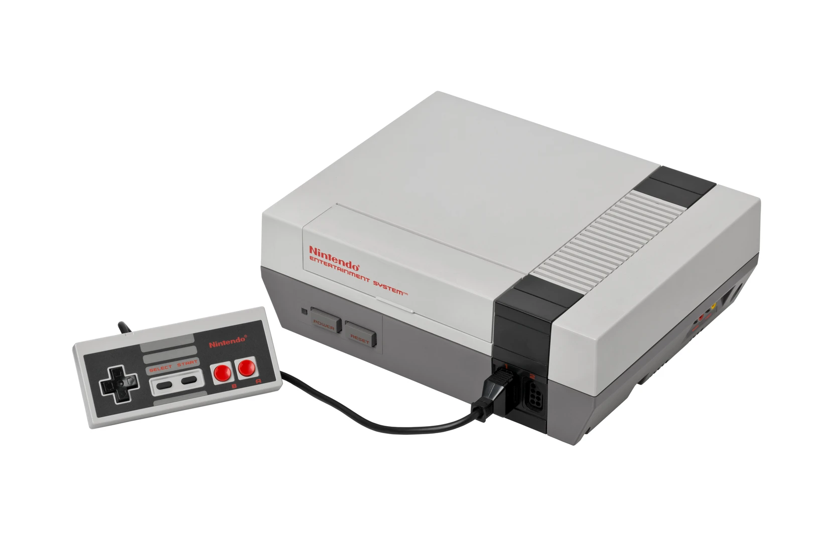
Cartridge in. Push it down. Close the gray door. Press Power.
For a moment, the television gives you nothing. Then a few colors and a few notes become a place you recognize. As a kid, that was explanation enough: you pressed a button, and Nintendo happened.
Inside the NES, something more interesting was happening. The cartridge had joined an electrical system. A processor had found its first instruction. Separate circuits were preparing pictures and sound, while the game began checking what your hands were doing.
Following that chain explains more than how an old console starts. It explains some of the things we remember most clearly about playing it.
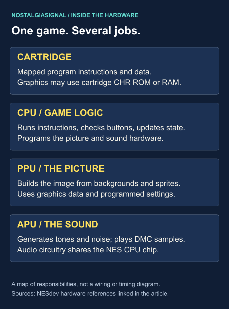
The CPU runs the game’s instructions and programs the picture and sound hardware. The PPU has its own graphics-memory access, while the audio circuitry is part of the NES CPU chip. A cartridge can therefore supply more than instructions alone. The CPU memory map, PPU reference and Rodrigo Copetti’s hardware analysis describe those roles in more detail.
The whole game did not have to “load” first
An NES Game Pak is more than a plastic container for a file. Through its connector, cartridge hardware becomes accessible to the console’s processors. The CPU can read program instructions and data from cartridge memory as the game runs.
That is different from copying an entire game into a large pool of RAM before starting. The NES does initialize memory and prepare graphics, but it can execute code directly from the cartridge’s mapped program memory. Those contacts are part of the working computer.
The distinction matters because the console has very little internal workspace: 2 KB of CPU RAM. That is not its total memory. Graphics memory and memory on the cartridge are separate parts of the story. Treating “2 KB” as everything the machine can use makes its architecture sound more impossible than it really is. NESdev’s CPU memory map shows how these regions fit together.
Where does the processor begin?
In a North American NTSC NES, the Ricoh RP2A03 contains a 6502-derived CPU running at roughly 1.79 MHz. A clock cycle is not the same as a complete instruction; instructions can take several cycles. NESdev documents the CPU and its timing.
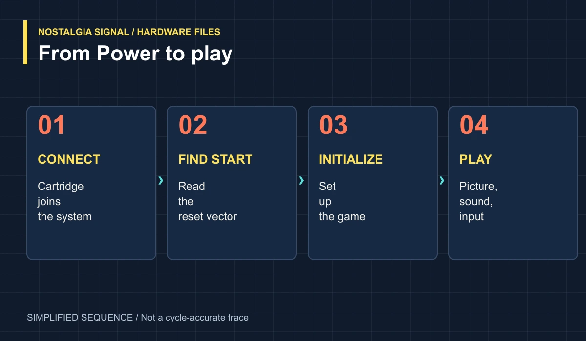
When reset ends, the CPU reads two bytes at addresses $FFFC and $FFFD. Together they form the reset vector: the address where execution should begin. The cartridge supplies that starting point through the console’s memory map.
There is no desktop to reach and no application icon to select. The CPU follows the starting address into the game’s code. That code then establishes the conditions the game needs: working memory, processor settings, cartridge hardware, graphics, and sound.
Why the red light sometimes blinked
The familiar North American front-loading NES also has a lockout system, commonly called 10NES. A CIC chip in the console communicates with a corresponding chip in a compatible cartridge. If that exchange fails, the console can repeatedly reset.
A poor cartridge connection can disrupt it, producing the blinking light and flashing screen many of us remember. That is one important explanation, not a diagnosis for every NES fault. Different hardware revisions and regions also matter. NESdev’s CIC reference describes the lockout hardware.
We mostly experienced this as a negotiation with a gray box: remove the game, insert it again, hope. The machine was dealing with electrical contacts and reset signals. We were trying to get back to the title screen.
A world assembled from little squares
The NES picture processing unit, or PPU, builds backgrounds from reusable 8-by-8-pixel tiles. A tile might be part of a brick, a letter, or a section of scenery. A nametable tells the hardware which tiles go where; other data selects their colors.
Moving objects use sprites, whose patterns also come from tile graphics. A character can be assembled from several hardware sprites. The console does not need a separate, complete picture of every possible moment in the game.
That reuse is why a small collection of patterns can become a screen full of scenery. Arrange the pieces differently, scroll through them, update the moving objects, and the player reads a continuous world. NESdev’s PPU overview explains the separate graphics address space.
The PPU also needs time after power-on before certain register writes take effect. Startup software accounts for that delay before configuring the picture. That brief wait is part of the work hidden between Power and the first screen. PPU startup behavior is documented separately.
Why characters flickered in busy scenes
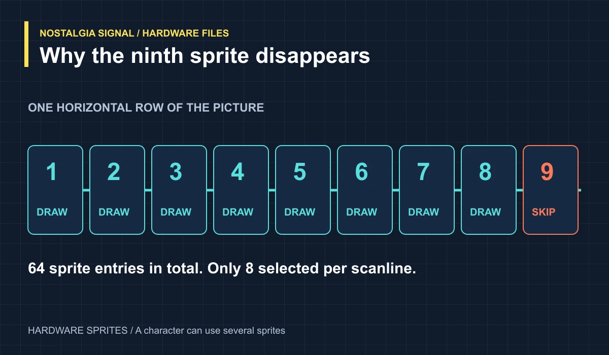
The PPU can select only eight hardware sprites for a single scanline. A scanline is one horizontal row of the picture. Because a large character may use several sprites, a few characters can already crowd that limit.
When too many sprites share a row, some will not be drawn. Games can change their ordering between frames so different sprites get a turn. To the player, that can look like flicker.
It is a useful distinction: the hardware imposes a limit, and the game chooses how to manage it. Flickering is not simply the console randomly forgetting an enemy. Often, you are seeing a deliberate compromise that spreads a visibility problem across several objects. The sprite-evaluation reference explains the selection process.
Your thumb becomes a bit
The standard NES controller does not send a command such as “jump.” It reports button states.
The console latches the controller’s state, then reads it serially: A, B, Select, Start, Up, Down, Left, Right. The game interprets those bits according to its rules. A might make Mario jump, confirm a menu selection, or do nothing at all. NESdev’s controller documentation gives the button order and reading behavior.
That small distinction is the entire relationship between the player and the software. Your thumb changes a contact. The contact changes an electrical state. The game reads a value and decides what should happen next.
Five voices, a whole musical identity
The NES audio hardware offers five main channels: two pulse channels, a triangle channel, a noise channel, and a delta modulation channel, or DMC, that can play samples. They are part of the RP2A03 package alongside the CPU. NESdev’s APU reference describes their roles.
A familiar arrangement might put melody on a pulse channel, bass on triangle, and percussion on noise. But that is a compositional choice, not a fixed rule. Sound effects also compete for the available voices, so a jump or explosion may temporarily interrupt part of the music.
Those constraints became a recognizable sound. Composers had to make each voice earn its place. The result could feel much bigger than the few circuits producing it.
The cartridge could make the old console more capable
Later games could bring additional hardware inside their cartridges. A mapper might switch which bank of program or graphics memory the console could access, provide extra RAM, or offer timing features.
Think of bank switching as changing the shelf visible through a window. The window stays the same size, but a different section of the library appears behind it. The console has not gained an unlimited address space; the cartridge changes what is mapped into the existing one. Capabilities vary by board. NESdev’s mapper overview covers those differences.
This helps explain why the NES library changed so much over its lifetime. Developers learned the hardware, and cartridges could provide tools earlier games did not have.
The limits are part of the memory
Once you know what is happening, the NES looks both smaller and more impressive. The chunky scenery, crowded-screen flicker, and unmistakable music have practical explanations. They also became the texture of an era.
The console never contained a miniature world. It contained the means to describe one, a little at a time, quickly enough for us to believe it.
Cartridge in. Power on. Somewhere to go.
Hardware scope: this article primarily describes the North American NTSC front-loading NES. PAL systems, the Famicom, and later revisions differ in timing and some hardware features.
Cover photograph: Evan-Amos, public domain. Original photograph on Wikimedia Commons. Diagrams: NostalgiaSignal.